Mazda 0000-8F-N02B Bedienungshandbuch Seite 6
- Seite / 26
- Inhaltsverzeichnis
- FEHLERBEHEBUNG
- LESEZEICHEN
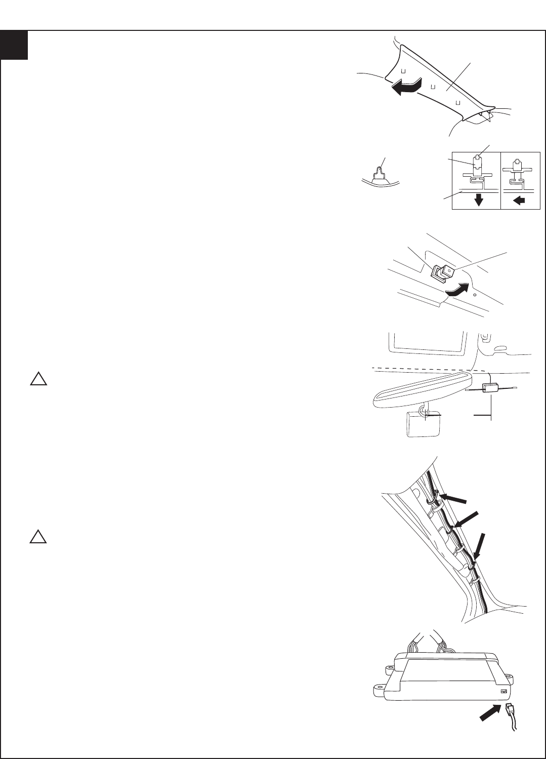
- INSTALLATION INSTRUCTIONS 1
- Connector on harness side 2
- View from harness side 2
- VEHICLE PREPARATION 3
- Plastic Nut 4
- Fig. 1-4 4
- Tie Wraps 5
- DIPOLE ANTENNA MOUNTING 6
- HOOD SAFETY SWITCH MOUNTING 7
- Unit-Light Auto Off 9
- Module 9
- VIEW FROM HARNESS SIDE 10
- FIGURE Z 11
- RE-ASSEMBLY 17
- WARNING: / AVERTISSEMENT 18
- TACHOMETER PROGRAMMING 19
- TRANSMITTER PROGRAMMING 20
- FUNCTION TEST 21
- TROUBLESHOOTING GUIDE 22
- SERVICE PART NUMBER LIST 24
- HOOD SAFETY SWITCH ADJUSTMENT 24
- SYSTEM LAYOUT 25
- FINAL INSPECTION 26
© 2020, manymanuals.de. Alle Rechte vorbehalten. | 1.036 s |
 Manymanuals.com
 Manymanuals.de
 Manymanuals.fr
 Manymanuals.it
 Manymanuals.pl
 Manymanuals.cz
 Manymanuals.es
 Manymanuals-pt.com
Kommentare zu diesen Handbüchern